2009/05/12 23:00:16
Sterling
that box looks neat, how are you going about setting up hydraulic clutch?
2009/05/12 23:13:04
fordsy
Don't need to. It's for a cable clutch. That's why there are only two masters on it, not three.
2009/05/12 23:16:52
joeyjonsey
where did you get that plenum rust repair section ?
2009/05/12 23:17:44
Sterling
both masters are for the brakes? fair enough.. how does that work? one for each side of the car?
2009/05/12 23:36:27
fordsy
quote:
Originally posted by joeyjonsey

where did you get that plenum rust repair section ?

Twin cam services in Frankston sell them. 03 9786 4711. They sent mine out in the post. Arrived next day.

quote:
Originally posted by Sterling both masters are for the brakes? fair enough.. how does that work? one for each side of the car?

One master for the front brakes, one for the rear brakes. The balance bar allows you to adjust the braking bias from inside the car by varying the ratio of push on the master cylinders.
2009/06/12 09:24:30
esc-078
quote:
Originally posted by fordsy

Here is another shot of the box. Doesn't look like there will be any fouling of the bar by the throttle.

Hmm.. just recieved a email from David at Gartrac. Here's a snippet.

quote:
MK2 HYD PEDAL BOX [GAR 6101] COST £324.64

YOU CAN NOT FIT O/E PEDAL, BIAS ADJUSTER IN THE WAY, GP4 THROTTLE PEDAL NEEDED[GAR6108] COST £51.87

WE BUILD THE PEDAL BOX WITH, 0.625" CYLINDER ON THE FRONT, 0.70" ON THE REAR BRAKES AND WITH 0.70" ON THE CLUTCH


I think the very top of the pedal where the cable attaches is where the concern is. Either that or they're trying to make more pounds by selling a GP4 throttle pedal as well [%].

With the current exchange rate, you might as well get a GP4 throttle pedal too. Price including delivery to AUS for a MK2 hydraulic clutch pedal box is 763.082 AUD!
2009/07/12 20:48:57
fordsy
Right. Back to the repair work.

The test fit of the heater worked a treat. Fits like it did before i chopped the bulkhead apart.

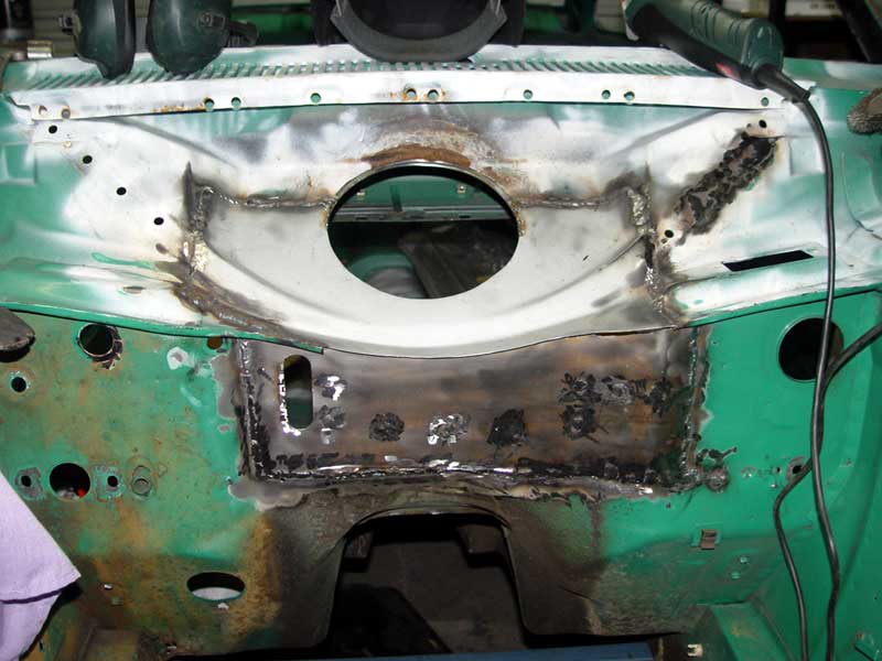
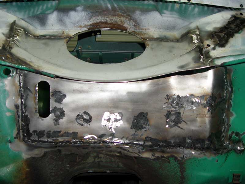
Top section of the front firewall was welded in today from the engine bay side. I'm saving the inside welding for one big hit as i'm trying not to start too many different things at once.


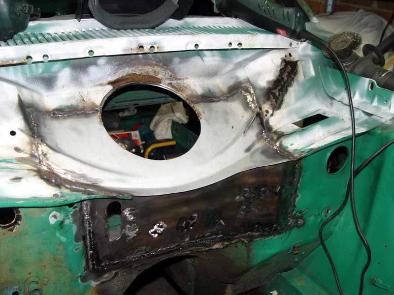
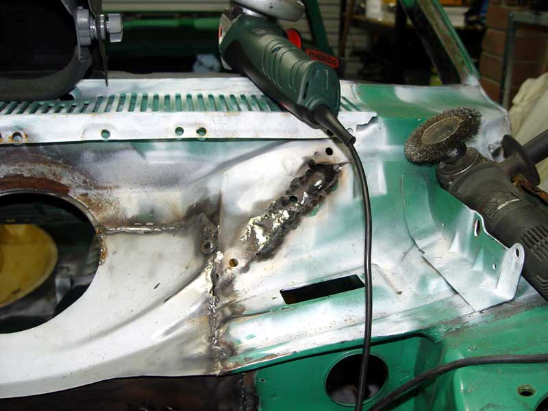
Next job is to roll the lip down against the firewall and seam weld it. This gives a little more room behind the rocker cover and helps to strengthen the firewall. That'll finish the engine bay side firewall welds then it's into the inside to finish off the lap welds, seam seal and paint.
2009/07/12 21:06:49
fordsy
My daughter is showing some good early signs of an interest in restoring cars. Here she is 'reading' my POR15 catalogue.

2009/08/12 20:42:38
fordsy
Just posting this here as i don't want to forget it and i'm trying to keep all my information in one place.

Exhaust manifold stud replacement = M8 X 20 Cap head bolts or hex head as required.

front wing retaining bolts = m8/lock/nut x 6
CAM IS JUST OFF DIAL IN SPEC TO AVOID VALVE DAMAGE IN TRANSIT. THERE IS A SCRIBE MARK ON THE BACK CAM JOURNAL AND TOWER, ONCE THE HEAD IS ON TURN THE CAM TO THESE MARKS AND FIT TIMING BELT. ONCE BELT IS FITTED AND TENSIONED INLET VALVE 2 AND EXHAUST VALVE 3 WILL NEED ADJUSTING.

BEFORE FITTING CAM COVER WIPE LUBE OVER CAM LOBES.

NEW OIL AND FILTER MUST BE USED AND OIL NEEDS TO BE A MINERAL BASED 20W/50, 25W/50 OR 25W/60 NO SYNTHETIC CAN BE USED.
OIL FILTER SHOULD BE PRE-FILLED.

ONCE ENGINE IS STARTED AND OIL PRESSURE IS UP ENGINE SPEED SHOULD BE TAKEN TO 2000-2500RPM FOR 20 MINUTES TO BED CAM IN.

AFTER 20 MINUTES CAM COVER NEEDS TO BE REMOVED, HEAD RE-TORQUED AND VALVE CLEARENCES CHECKED.

FUEL WILL NEED TO A MINIMUM OF 95 OCTANE.
DON’T USE SHELL FUEL, MOBIL, BP AND CALTEX ARE BEST.

SPARK PLUGS WILL NEED TO BE NGK AP6 OR 7FS.
PLEASE NOTE SPARK PLUGS MUST BE FITTED WITH EARTH ELECTRODE BETWEEN 4 O’CLOCK 8, MARK THE HEX OF PLUG WITH A TEXTER IN LINE WITH ELECTRODE AND CHECK ONCE TIGHT, PLUGS MAY REQUIRE SWAPPING TO ACHIVE THIS, IT’S WORTH BUYING TWO SETS AT A TIME JUST IN CASE.

IGNITION AND CAM TIMING AS WELL AS JETTING MUST BE SET ON A DYNO.

SPEC.

CAM RL30

CLEARENCES IN .010” EX .012”

CAM TIMING INTIAL USING LIFT @TDC .125” INLET NUMBER 1

COMPRESSION RATIO

HEAD 43CC

HEAD GASKET SUPPLIED 6.79CC

RATIO FOR STANDARD LC ENGINE 10.88:1
“ “ “ HC “ 10.94:1
“ “ “ ENGINE WITH FLUSH DECK HEIGHT 11.01:1
“ “ FOR + .040” FLUSH DECK HEIGHT 11.23:1

COMPRESSION RATIO CAN BE RAISED BY USING A .030” HEADGASKET.

FLOW TEST RESULTS.
TEST CARRIED OUT @25” LIFT INL EX
100 59 59.5
150 85.5 78
200 116.6 98.5
250 139 100
300 155 110
350 158.3 120
400 169 126
450 179.4 131
500 183.5 136.4
550 189.5 -
OVER ALL EXHAUST % AVERAGE IS 79.7%
LOW LIFT EXHAUST FLOW % IS HIGH TO HELP CYLINDER SCAVENGE.
EXHAUST FLOW %AVERAGE FROM .250” ON IS 73.45%.

2009/09/12 01:06:17
joeyjonsey
do you really need to weld the inside of the repaired sections i would of thought with thin steel it wouldn't matter hows about sikaflex ?
<< ..78.. >> - Powered by APG vNext Trial

© 2025 APG vNext Trial Version 5.1

Use My Existing Forum Account

Use My Social Media Account